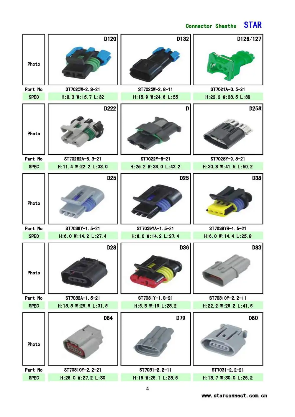

I would call them first and see if they’ll give you “samples” of all the Yazaki parts needed. SMD Inc is your best bet, but they require a $100 minimum order. Yazaki parts are hard to come by in small quantities.

By my estimate I could assemble the equivalent for less than 10. It is basically a standard rocker switch, three lengths of 18 gauge wire, three butt connectors and a plug that connects this wiring to the control unit that is furnished with the Power Steps.

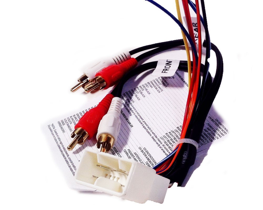
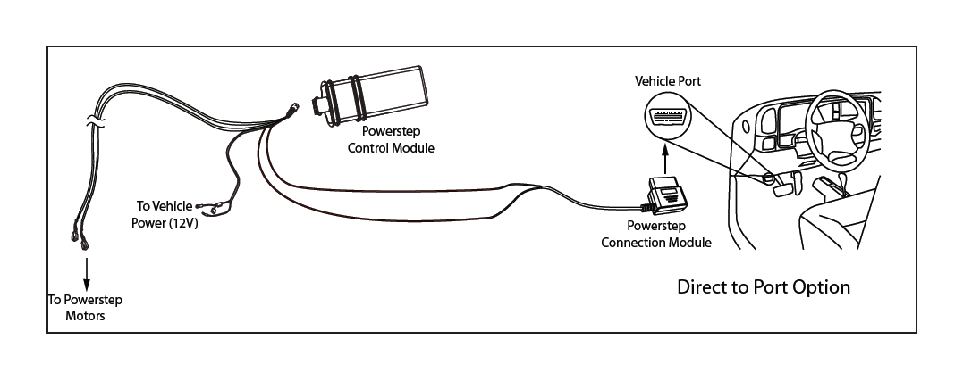
I can mail you some in a standard letter if you want) This override switch is a very overpriced accessory for the AMP Research Power Steps. (These are only available in 100 quantities at mouser. The easiest way to do this is to run a wire from the battery to the amp. (2) star can IHS connector terminals- TE Connectivity 5-963715-1 - The next step is wiring the car stereo amplifier. (1) star can IHS connector- TE Connctivity 2-2138650-1. (2) step motor connector empty position seal plugs- molex 34345-0001. (10) step motor connector terminals- molex 33012-2002. (6) step module C2 connector small terminals- Yazaki 7116-4720-02 (2) step module C2 connector large terminals- Yazaki 7116-4110-02 (same as C1 terminals, so 6 all together) (1) power step module C2 connector- Yazaki 7283-8599-30 (4) power step module C1 connector terminals- Yazaki 7116-4110-02 (1) power step module C1 connector- Yazaki 7283-8398-40 (1) Power distribution center C6 connector terminal- Yazaki 7116-4120-02 Here’s all the parts you need to build the harness: I’m no good at doing drawings on a computer, but here’s a crude sketch. Use Tesa tape for interior wiring, and use super 33 tape and split loom for exterior wiring. There are detailed pics of the star can IHS connector block location in the above document. Attach the ground wire near the power step module, as there will already be a common ground bolt at the footwell in that vicinity. Then, once you branch off the wiring to go to the two motor connectors and fuse box connector, cut them to length and finish pinning the wires to the rest of the connectors. Assemble the wires to the C1 and C2 power step module connectors, and leave the other connectors off for now so you can pass the wire bundle through one location in the firewall that you choose. No sense in figuring out which connector it terminates at, and adding more terminal part numbers in the mix.
#Amp steps wiring harness install
If the fuse box C6 connector pin 22 wire is already present, just remove it and install your wire. This method will bypass all inline connectors, and remove all doubt on what partial wiring may or may not be present. Using your best guess, cut all the wires long enough (longer) to reach their appropriate spots with all wires originating at the power step module. The way I would do this is, I would install all the parts first, then the harness. The wire sizes are listed in mm2, so convert those to AWG when choosing wire. It includes the schematic, connector views, and pinouts. Here’s some info I put together on the power steps.


 0 kommentar(er)
